IST-2001-33522 OMEGA
Correct Development of Real-Time Embedded Systems
Project case studies

|
EADS SPACE
Transportation case study
description This case study presents an extract of the Flight Software of the
European Ariane 5 Launcher and focuses on relevant
real time behaviours. The objective of this Ariane 5 Flight Software
is to control the launcher mission from lift-off to payload release. This
software operates in a completely automatic mode and has to handle both the
external disturbances and the hardware different failures that may occur during
the flight. This case study presents the most relevant points required for such
an embedded application and focuses on the real time critical behaviour. Stages
The launcher is composed of 3
stages: EAP stage, EPC stage and ECS stage.
Mission
The mission is composed of several phases, each one corresponding more
or less to the permanent working point of a launcher stage. At the end of a
permanent working of the launcher, a transition is performed to reach a new
permanent working. This case study models the two first phases of the flight
and the associated transitions: 1.
Ground phase
2.
Transition
from ground phase to EAP phase (lift-off) The lift-off procedure starts by a EPC (Vulcain
engine) ignition. The Vulcain engine is monitored
during some seconds (pressure, temperature, thrust …).
3.
EAP Phase
4.
Transition from
EAP phase to EPC Phase (EAP release) During this transition, EAP are released.
The control / command shall take dynamically into account the change of
the launcher configuration: only one engine (EPC) shall be controlled instead
of 3 previously (EPC+2 EAP), some sensors in the EAP are lost. The NEXT phases (EPC, ECS and BAL) are not described in this case study. Modelling and verification examples An embedded
space software such as the one of the Ariane 5
launcher presented above is composed by several modules which can have
different types of behaviours but which always strongly interact (from a
functional interface point of view and/or from a real time point of view).
Roughly speaking, it exist two main types of functional behaviours: -
cyclical synchronous
execution (i.e. all the processes have a specific period and phase; they
received their inputs at the start of their periods and shall produce their
outputs before a given delay, which shall not be greater than their execution
period) -
non cyclical
execution (synchronised or not with the cyclical synchronous process depending
of their required precision; their execution can depend from a date or from a
process external event). Examples of
these two types of behaviour are given below. In order to
validate (by simulation or by proof) the software behaviour, a part of the
environment shall also be described. The environment can contain part of the
spacecraft hardware (valves, pyrotechnic commands…), the physical environment
(ground control centre, wind for an atmospheric phase, star and moon for some
sensors, other spacecraft…), and part of the software (or more generally of the
computer based system) which is not described in the model (as a numerical
algorithm, a bus protocol, etc). Some examples of environment description are also given
below. Software
modelling: asynchronous behaviour
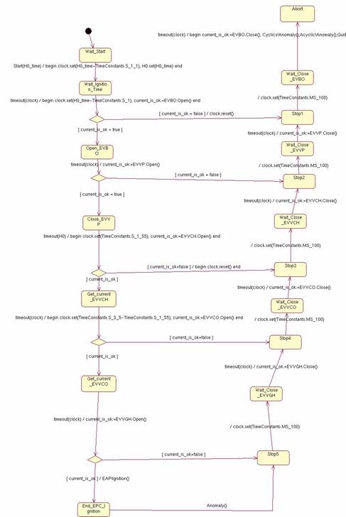
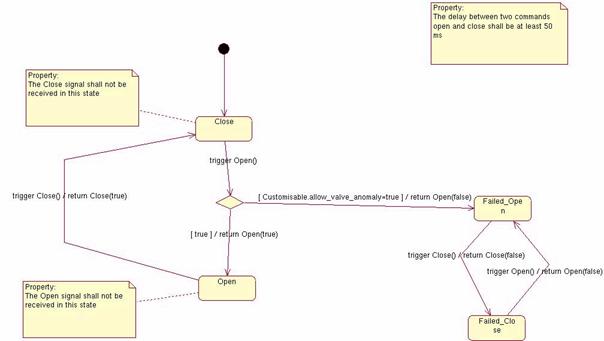
The following
automaton is an example of asynchronous behaviours of the flight software. It describes
the EPC behaviour. The EPC
behaviour has the particularity to include the immediate recovery following
failure detection. In the following automaton, the left part describes the
stage ignition sequence. The right part describes the stage stop sequence.
Depending on the step where the anomaly has been detected, the stop sequence
shall start at a different point (these sequences are a simplification of the
real ones). These two sequences are timed.
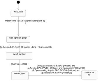
The lift-off is characterised by the ignition of the Pyro1
object. Thus, this property is informally specified in the following way: If the Pyro1 object (of class Pyro)
entries the state “Ignition_done”, then: -
All the instance of the valve class
shall be in the “Open” state 2 seconds after the transition of a pyrotechnics
command automaton to the “Ignition_done” state and
then remain in this state forever. The following automaton formalizes this property:
The
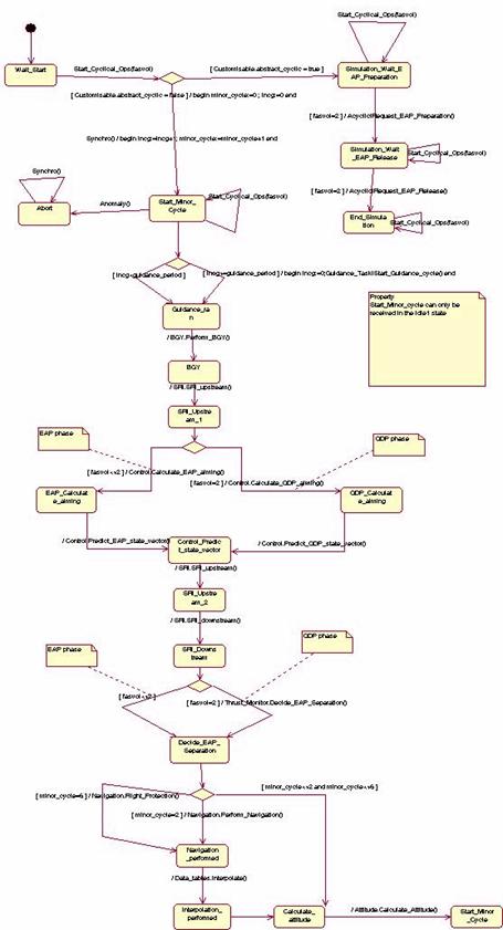
software model: cyclical synchronous behaviour
The following
automaton specifies a basic cycle execution. It describes the sequence of the
flight control command algorithms (navigation, guidance, control). It is
periodically activated
In order to verify the correctness of the real time software
design, this case study constains also the
description of the multitasking (task or thread definition, priorities between
tasks) and the CPU consuption of each algorithmic function (associated to a
task). For each task, a constant priority is
defined in the task constructor:
Then, each function can declare its CPU
cunsumption:
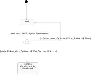
Example of
property: The main property of the basic cycle is to finish its
execution before its deadline (i.e. before being requesting to restart a new
execution cycle). This property is formalised by the following automaton. The “synchro” signal, which commands the start of a software
cycle, shall be received only in the “idle” state, i.e., when the treatments
associated to the previous cycle are achieved.
The
environment model: a valve
The following
automaton describes a valve behaviour with its
potential failure scenario. When an open command is received, the valve can
reject the command and enter a failed state.
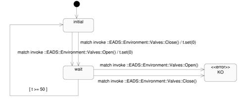
This property is formalized by the following automaton. When
one of the two signals “Close” or “Open” is received by the valve from the
software, a timer (named “t” in the example) is armed. If another signal is
received before 50ms, the automaton enters an error state.
The
environment model: the 1553 bus
The flight control computer communicates with the launcher
equipment with a 1553-MIL bus. The 1553 bus protocol uses an exchange memory
between application software and the hardware bus. The chronology is the
following: -
For a command sent to a piece of
equipment (receive transfer in the 1553 terminology): -
The application software writes in the
exchange memory. -
At a predefined time, the low-level
software read the exchange memory and performs the physical bus transfer. -
For a measurement read from a piece of
equipment (transmit transfer in the 1553 terminology): -
At a predefined time, the low-level
software performs the physical bus transfer and writes the exchange memory. -
The application software reads in the
exchange memory. The application software shall not read or write the
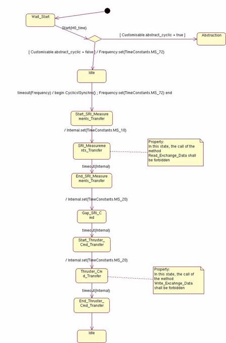
exchange memory at the time foreseen for the low-level transfer. In order to respect the real time properties (between a
measurement read from the bus and a command write on the bus), a bus frame is
constructed, i.e., a timed slot is allocated to each transfer. This is described by the following automaton:
This previous property can then be expressed by: -
In the state SRI_Measurements_Transfer,
the method Read_Exchange_Data shall not be called. -
In the state Thruster_Cmd_Transfer,
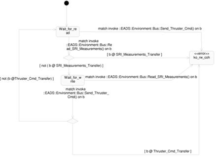
the method Write_Exchange_Data shall not be called. This property has been completed by a property of sequence
between the measurement and the command. If the software behaves correctly, a
measurement shall always precede a command. Thus, this property has been
formalised by the following automaton:
|