IST-2001-33522 OMEGA
Correct Development of Real-Time Embedded Systems
Project case studies

NLR case
study description
The case
study involves the Medium Altitude Reconnaissance System (MARS) deployed by the
Royal Netherlands Air Force on the F-16 aircraft. The system employs two
cameras to capture high-resolution images. The MARS counteracts the image
quality degradation caused by the forward motion of an aircraft by creating a
compensating motion of the film during the film exposure. The controls applied
to the camera for the film speed of the Forward Motion Compensation (FMC) and
the Frame Rate are being computed real-time based on the current aircraft
altitude, ground speed, and some additional parameters. The system is also
responsible for producing the frame annotation containing time and the
aircraft�s current position, which must be synchronised with the film motion.
The system also performs health monitoring and alarm processing functions.
Schematic representation of the MARS The MARS
software is responsible for the following system functions:
Camera and film exposure control In order to
perform the camera and film-exposure control functions system acquires the
current altitude and velocity data from the avionics data bus of the aircraft.
Based on these values it computes the film Frame Rate to be used and the value
for the Forward Motion Compensation (FMC) signal. The computed values are sent
to the Trigger & Exposure Module via a serial link. When pilot depresses the
camera trigger button, the Trigger & Exposure Module generates the trigger
pulses (with the computed Frame Rate) and applies the computed FMC signal to
the film transport control of the camera. Film annotation
In order to
perform the film annotation functions system acquires the current navigation
data (latitude, longitude and heading) as well as time-of-day value from the
avionics data bus of the aircraft. It formats the data and sends it to the Annotation
Module via the serial link. After the completion of each frame exposure cycle
the camera halts the film and issues an annotation request to the Annotation Module.
Upon reception of this request the Annotation Module provides the current annotation
data to the camera via a serial link. After the reception of the annotation
data the camera annotates current frame. The annotation cycle must be completed
before the next frame exposure cycle begins. Health monitoring and
alarm processing
In order to
perform the system health monitoring and alarm processing functions system
processes the operational status of the various MARS components (e.g. camera
status, serial communication status, data bus status, statuses of the hardware
modules, etc.) and generates pilot alarms according to the alarm processing
logic. System properties
The
following system properties characterise the subject of the case study: �
The
deadline on response to the annotation data request from the cameras, which
also includes the data transfer time; �
Hard
timing requirement on the age of annotation data supplied to the camera, which
includes the total data processing time from acquisition to proper formatting; �
Hard
timing requirement on the age of data used for the exposure control, which
includes the total data processing time from acquisition to generation of the
control signals; �
Hard
timing requirements on the data acquisition and processing time in order to
accommodate the data rate of the avionics data bus. The system performs asynchronous data
acquisition from the avionics data bus, while performing concurrent cyclical
internal processing with several different cycle times: �
Data
processing; �
Data
transfer to the annotation and trigger & exposure modules via the serial
link; �
Health
monitoring and alarm processing; �
Control
Panel display update; �
Control
Panel commands processing. Environment
constraints and properties
Environment�s
non-deterministic nature with its influence on the system operation is in the centre
of the case study. The following constraints and properties of the environment played
major role in the case study:
Modelling and verification examples High-level
requirements modelling Untimed
modelling and verification Timed modelling
and verification High-level requirements modelling
The high-level requirements modelling is
performed with the use of LSCs and the PlayEngine tool. The LSC model is based
on the subset of the software system requirements of the MARS case study. The
following activities have been represented:
The model is
time-driven and contains some timing constraints specifications derived from
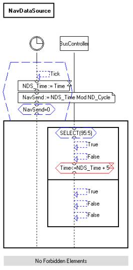
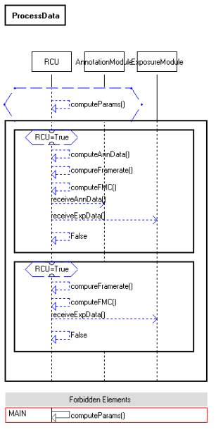
the requirements. Below are examples of the case study LSC model.
LSC of the Navigation data source
LSC of the data processing Next to the
LSC modelling several verification experiments have been performed on the
developed model using the model verification facility provided by the
PlayEngine tool, which makes use of the SMV model checker. Below are some
property LSC specifications used in the verification experiments.
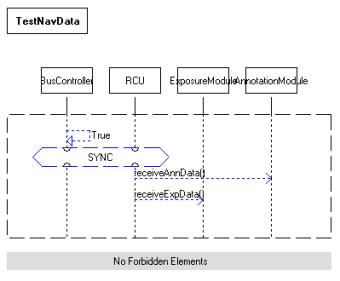
Property:
If a Navigation data message has been acquired by the BusController, the RCU
(Main Module) will eventually transfer the new Annotation data to the
AnnotationModule and Exposure data to the ExposureModule
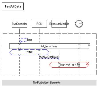
Property: If an Altitude data message has been acquired by the BusController, the
RCU (Main Module) will transfer the new Exposure data to the ExposureModule at
most 70 time units later Untimed modelling and verification Untimed UML
modelling is performed with the use of Rhapsody tool from I-Logix. For the
purpose of untimed verification experiments the UML Verification Environment
(UVE) tool from OFFIS is being applied to the data acquisition part of the MARS
model. The UVE tool provides facilities for untimed model checking of UML
models. Property specification in the UVE tool is based on propositional logic and
temporal logic patterns. The case study model is event-driven with non-deterministic
external event trace being used to drive the behaviour of the environment. To provide
for environment�s liveness and to restrict its full non-determinism the temporal logic-based assumptions are
used. Some examples of the case study UML modelling are given below.
Air data acquisition class diagram
Statechart of the DatabusController
Statechart of the MessageReceiver UVE tool
provides a synchronous view on the system. A system run is seen in terms of run-to-completion
steps representing a sequence of system configurations. Execution traces
generated by the tool are represented in the form of discrete-time timing
diagrams. The tool�s built-in temporal logic patterns use the discrete-time
quantifications in terms of run-to-completion steps in order to express the
bounded property specification, e.g. �if P then eventually Q within X steps�.
The verification experiments made extensive use of this style of property
specification in order to more closely relate the untimed verifications to the
timed ones performed with the other OMEGA tools. An example shown below is one
of the series of verification experiments performed in the case study. Property: If the DatabusController becomes henceforth
not operational then eventually the MessageReceiver will be in the
ControllerError state. Two assumptions are specified for this property
verification:
Tool
output with the verification result Timed modelling
and verification UML
modelling for timed verification experiments is performed with the use of
Rhapsody tool from I-Logix. Modelling of the timing is performed with the use
of OMEGA time extensions. For the purpose of the timed verification experiments
the same part of the UML model of the MARS case study has been taken as for the
untimed verification experiments with the UVE tool. For the timed verification
experiments the IFx tool from VERIMAG is used. The IFx tool provides facilities
for timed model checking, making use of the OMEGA time extensions, as well as
model simulation. Property specification in the IFx tool is based on observers.
The case study model is event- and time-driven with explicit timed modeling of
the environment, which exhibits non-deterministic behaviour. Some
examples of the case study UML modelling are given below.
Air data acquisition class diagram
Statechart of the NavigationDataSource
Statechart of the MessageReceiver The IFx toolset from VERIMAG provides
facilities for use of the OMEGA time extensions in UML models, allowing
simulation of the timed models and verification of, among others, timed
properties. Properties to be verified are expressed in terms of observers,
which are defined in the form of specialised statecharts within the dedicated
<<Observer>> classes. The error traces generated during the
verification process are used as system execution scenarios by the IFx
simulator for the model debugging purposes. Series of verification experiments
are performed for the specified properties. Below are several observer
specifications used for the verification of the corresponding properties. Property 1: If the DatabusController becomes non-operational at time T and stays
non-operational for more than 10 ms then the MessageReceiver shall enter the
state ControllerError by the time T+10 ms at the latest.
Observer for the Property 1 Property 4: If the
MessageReceiver is in the BusError state and both the AltDataSource and the NavDataSource send successfully their data during
the 2 consecutive cycles, then the MessageReceiver will be at Operational state
at most 5 ms after the last of these messages has been sent. Property 5: The MessageReceiver shall not enter the
Operational state unless 2 previous attempts of both data sources to transmit
message have been successful. Compositional approach has been adopted for specification of
the Property 4 / Property 5 observer.
Class diagram of the Property 4 / Property
5 compositional observer
AltitudeDataSource observer for the
Property 4 / Property 5 composition
NavigationDataSource observer for the
Property 4 / Property 5 composition
Main observer for the Property 4 /
Property 5 composition |