Tool description
The UVE tool (UML Verification Environment)
serves to check functional and qualitative temporal properties of the
Omega kernel model - structure, behavior and the order of the object communication - combining them into (temporal) formulas. It can be applied at the design and implementation phases for the component verification when real-time constraints are not yet specified. Only requirements with discrete-time can be taken into account, i.e. only with relative time durations, related to the number of steps in the model execution. UVE considers a fine-grained notion of a step, corresponding to transition firing or event discarding.
Main functionality of UVE:
-
Verification of a set of temporal logic formulas (defined via the provided patterns): check of reachability, invariance, liveness, safety etc.
- Verification of LSCs: a compliance check between specifications and a design.
-
Sequence diagrams generation: (a) as witness-paths for properties reachability and existential LSCs; (b) as counterexamples - error-paths - for so called invariant properties such as, e.g., universal LSCs.
- Results visualization with symbolic timing diagrams (STDs) and LSCs.
- Verification of requirements under different kinds of assumptions, restricting the non-determinism of the environment or of the system behavior (e.g., not yet implemented parts).
UVE consists of two components :
-
Rhapsody-based, RUVE: the development was started in the
AIT-WOODDES project and extended with some modeling and specification features (in particular, with some object-oriented elements) as well as abstraction techniques in the OMEGA project;
- XMI based (over XMI file format, Rhapsody dialect) - XUVE - developed in the
OMEGA project.
The kernel of the currently implemented UVE architecture is depicted below, where the verification engine is shown together with the ways of its integration with modeling, specification, and third-party tools:
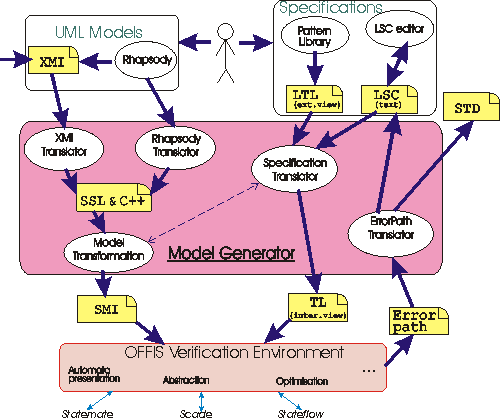
In difference to RUVE, XUVE
adds the following functionality:
- the semantics defined in OMEGA:
- non-determinism between concurrent regions in statecharts;
- non-determinism between enabled transitions;
- OMEGA Action Language (in addition to C++) with extended constructs for non-deterministic choice and concurrency;
- Two possibilities of the fine-tuning and invocation of the
verification process:
- using the Rhapsody graphical interface;
- invocation from a command line without a UML tool.
The final tool-set will be extended with the means to derive symmetry property of the whole model from the properties of its parts. This tool-extension is an implementation of the theoretical investigations of the symmetry reduction techniques (performed in cooperation with the Oldenburg Carl von Ossietzky University) and is intended to be used to reduce verification complexity as well as for the verification of unbounded models.
The complete architecture of the UVE tool-set expected at the end of the
OMEGA project (and already partially implemented) is depicted below:
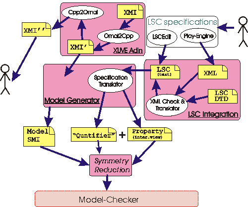
On this figure: Model Generator is the kernel shown on the previous figure above; XUVE AdIn is a component translating Rhapsody XMI format (with C++ actions) into the XMI with Omega Action Language ( OMAL) and back, allowing exchange between different UML tools; LSC Integration is a component providing LSC translation from the OFFIS format to the chosen XML format and back, which aims at specification exchange between different LSC tools; Symmetry Reduction component (currently under development) implements the mentioned above theoretical results for the verification of a larger class of LSCs.
Verification Examples
The MARS model (p.36-44)
developed by NLR within the Omega project was verified with UVE against several
un-timed
properties. In case the universal property does not hold or existential property holds, UVE generates an error-path or witness-path, resp.,
providing the result in three formats:
as a simple text, a sequence diagram, and a symbolic timing diagram (STD).
-
Below are figures corresponding to these formats of the verification result for the following (temporal) property: "Each time when DatabusController encounters an error, MessageReceiver will
detect this at the next step." The
property was considered under the following assumptions: (a) if DatabusController encounters an error, it remains to observe the error; (b) ControllerMonitor is activated to poll the current system state cyclically not later than each 5 steps.
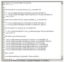
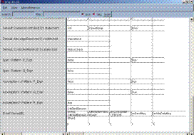
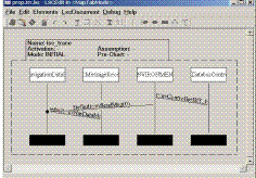
(click on the figures to get larger views)
STD shows evaluation of all elements in the model and specifications (objects, event queue, attributes, statecharts' states, premises and conclusions of the assumptions and commitments). In particular, at the third step of the system execution, the premise of the main property became true (DatabusController is in Error state), but the property's conclusion at the next step is false (MessageReceiver is in state Operational). Thus, the shown execution trace is an example of the specification violation. The sequence diagram shows the message exchange between the objects, leading to this erroneous situation.
- Another example, shown below, illustrates the results of the verification of the following LSC (where, the commitment LSC was checked under 2 assumptions specified as parts of the complete LSC specification):
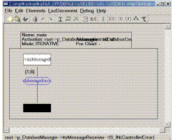
Two kinds of assumptions are considered: initial - activated once at the beginning of the system execution - and invariant - activated and evaluated infinitely many times, at each step of the system execution. The checked LSC corresponds to Property 1 from the MARS model (specification on p.36 and p.37-39) without additional assumption on the persistence of the DatabusController's error. The result of the verification as an STD and sequence diagram below shows an error.
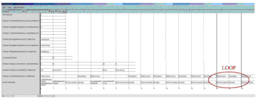
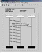
(click on the figures to get larger views)
STD and sequence diagram show that there is an infinite system run (with a cyclic repetition of the loop), satisfying both assumption LSCs and violating the commitment LSC: DatabusController entered state Error at the 5th step and exited it at the next step, so that ControllerMonitor, polled too slowly, can not detect this, and MessageReceiver always stays in state Operational.
Resources
Several documents are available from the Omega web-page, containing the descriptions of UVE and its parts:
- Conference paper presenting UVE:
I. Schinz, T. Toben, Ch. Mrugalla, B. Westphal,
The Rhapsody UML Verification Environment , In Proceedings of the 2nd International Conference on Software Engineering and Formal Methods (SEFM 2004), IEEE September 2004.
- Conference paper presenting a UML semantics used by UVE:
W. Damm, B. Josko, A. Pnueli, A. Votintseva,
Understanding UML: A Formal Semantics of Concurrency and Communication in Real-Time UML, In Proceedings of the 1st Symposium on Formal Methods for Components and Objects (FMCO 2002), LNCS 2852, 2003.
-
UVE Tool User Documentation (Guide, Tutorial, Restrictions), 2004.
-
Adapting and optimizing un-timed model checking tools to UML , In:
Omega Report, Milestone IST/33522/WP 2.2/M2.2.3 (appendix), June 2003.
- Presentation at Brussels on September 11, 2003:
Formal Verification of UML Models against Functional Properties
- Short description of UVE:
Untimed UML Verification Environment UVE,
In:
Tool set and methods for system verification, Omega Report, Deliverable IST/33522/D2.2.2, May 2004, pp.10-15.
- LSC description for UVE:
LSCs as Requirements for the Discrete-Time Verification Tool,
In: Omega Report, Deliverable IST/33522/D2.2.2-Annex 5, May 2004.
Download
The recent version of the complete UVE tool-set can be requested for the evaluation. To get download instructions, please contact "Omega in OFFIS".
The following platforms are currently supported:
|
